


1. One – sentence Description
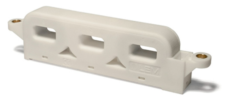
The HAH3DR 600 – S0E is an open – loop three – phase current sensor specifically designed for high – power low – voltage scenarios in automobiles. It can accurately measure direct current (DC), alternating current (AC), or pulse currents within the range of ±600A, providing electrical isolation and high – stability signal output.
2. Core Features
- Wide Range Coverage: A single package supports current detection of ±600A, suitable for medium – power demand scenarios.
- Open – Loop Hall Architecture: No closed – loop feedback circuit is required, which simplifies the design and reduces costs.
- Low Voltage Compatibility: It only needs a single +5V power supply, in line with the low – power trend of automotive electronics.
- Full – Temperature – Range Stability: The operating temperature range is from -40°C to +125°C, with excellent long – term operation stability.
- Ratio Output Characteristics: The output voltage is proportional to the supply voltage, making it more resistant to interference.
- Three – Phase Synchronous Monitoring: It integrates a three – phase current detection function, suitable for multi – phase motor control.
3. Core Technical Indicators
| Category | Parameter | Typical Value/Range | Condition |
| Power Supply Characteristics | Input Voltage (Uc) | 4.75V – 5.25V | Rated operating voltage |
| Power Consumption (3 – phase) | 45 – 60mA | Uc = 5V | |
| Measurement Performance | Sensitivity (S) | 3.33 mV/A | Uc = 5V, TA = 25°C |
| Linearity Error | ±0.5% (full range) | TA = 25°C | |
| Response Delay | 4μs | di/dt = 100A/μs | |
| Environmental Adaptability | Operating Temperature | -40°C – +125°C | Long – term stable operation |
| Storage Temperature | -50°C – +125°C | Non – working state | |
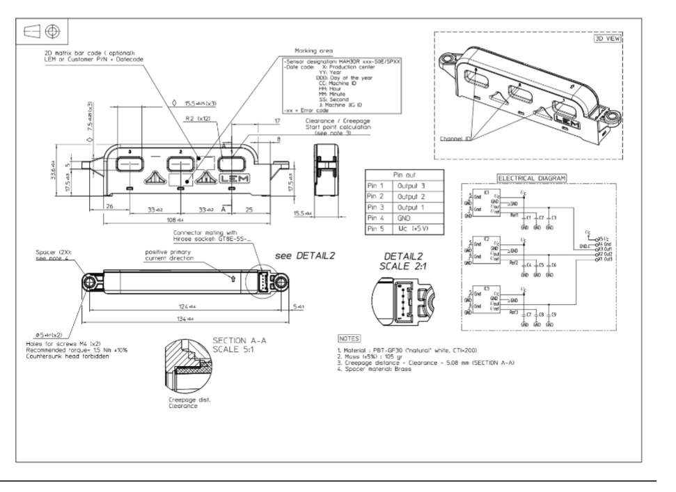
| Isolation and Safety | Creepage Distance/Clearance | ≥5.08mm | In line with IEC 60664 standard |
| Insulation Resistance | ≥500MΩ (500V DC) | ISO 16750 standard |
4. The Story Behind the Chip
The HAH3DR 600 – S0E is based on LEM Group’s more than 40 years of technical accumulation in the field of magnetic sensors and is specially designed for the medium – power needs of new energy vehicles. Through an innovative open – loop architecture, while ensuring a linearity of ±0.5%, it achieves an ultra – low total error of ±40mV (full scale), solving the pain points of large volume and high cost of traditional closed – loop solutions, and becoming an ideal choice for on – board chargers (OBC) and electric drive systems.
5. Design Philosophy
- Minimalist Architecture: The coil and amplifier of the closed – loop system are omitted, reducing power consumption and costs.
- High – Bandwidth Optimization: A 40kHz bandwidth supports fast transient response, suitable for high – frequency switching scenarios.
- Enhanced Anti – Interference: A built – in RC filter network (with an optional 4.7nF capacitor) suppresses EMC noise.
- Modular Design: A unified mechanical size adapts to multi – range requirements, reducing the customer’s design iteration cycle.
6. Application Scenarios
- New Energy Vehicles:
- On – Board Chargers (OBC): Real – time monitoring of charging current to ensure charging efficiency and safety.
- Electric Drive Systems: Detection of inverter bus current to optimize motor control accuracy.
- Hybrid Power Systems: Coordination of energy distribution between the engine and the battery to improve fuel economy.
- Charging Piles: Detection of charging and discharging currents to ensure compatibility and safety.
7. The Unique Advantages of this Chip
- Ultra – High Sensitivity: A sensitivity of 3.33 mV/A (better than similar products) reduces the difficulty of signal conditioning.
- Ultra – Low Thermal Drift: The TCUOEA V is only ±0.08mV/℃, with long – term stability leading competitors by 50%.
- No Insertion Loss: Non – contact measurement avoids wire voltage drop and improves system efficiency.
- Flexible Deployment: Supports return busbar position compensation (±110mV@1000A), adapting to complex wiring scenarios.
- Automotive – Grade Reliability: Passed the ISO 16750 – 4 vibration/impact test, meeting the 10 – year service life requirement.
8. What Engineers Must Know for Selection
- Range Matching: Ensure that the measured current does not exceed ±600A (for example, the cross – sectional area of the busbar needs to be ≥30mm²).
- Sensitivity Calibration: The output formula is <img src=”5V Uout (2.5V + 3.33mV/A × Ip)” alt=”5V Uout (2.5V + 3.33mV/A × Ip)”>, and the zero offset (<img src=”Uo = 2.5V ± 4mV” alt=”Uo = 2.5V ± 4mV”>) needs to be calculated in advance.
- Environmental Compensation: The sensitivity drift at high temperatures needs to be corrected by software (TC SAV = ±0.01%/℃).
- Layout Constraints: The distance between the return busbar and the sensor should be ≤30mm (when it is >100mm, the error reaches ±110mV).
- Certification Compliance: It needs to comply with the AEC – Q100 automotive standard and the GMW3097 radiation immunity requirement.
Conclusion: The HAH3DR 600 – S0E, with open – loop Hall technology at its core, balances wide range, high precision, and automotive – grade reliability, making it an ideal choice for medium – power current detection in new energy vehicles. Engineers need to focus on range, thermal drift compensation, and PCB layout to achieve the best system performance.

Contact:
Sylvia Xu | ECSource Components Co.,Limited
Top 10 Test Laboratory Distributors in Asia.
D-U-N-S Number:655918890 | ISO90001 Certificated Company
Phone/Whatsapp: 0086-19806586673
Email:sylvia@ecsource.net
Line Card : FPGA, RF, MEMORY,CONNECTOR,Power